The Practice of Catheter Cryoablation for Cardiac Arrhythmias
Edited by Ngai-Yin Chan


Cases
Case 2.2. Interesting case of a pediatric patient with Wolff-Parkinson-White Syndrome
This is a 2-year-old girl (13.5 kg) with Wolff-Parkinson-White (WPW) syndrome and a normal heart structure. She had an interesting initial history: She presented as an infant with heart failure symptoms at a different hospital. She was found to be in a rapid narrow complex tachycardia. This tachycardia did not respond to adenosine or to DC cardioversion (no tracings available). She was started on amiodarone, and this controlled her tachyarrhythmia. Her heart function showed full recovery. The thought at the time was that this was potentially ectopic atrial tachycardia and the WPW syndrome was a bystander.
Since her initial presentation, she had remained on amiodarone with no recurrent tachycardia. She has no reported side effects to the amiodarone currently. However, there was concern for long-term amiodarone therapy. The amiodarone was discontinued, and she was scheduled for esophageal study for evaluation of her prior tachyarrhythmias as well as risk stratification of her accessory pathway. See Figure 1.
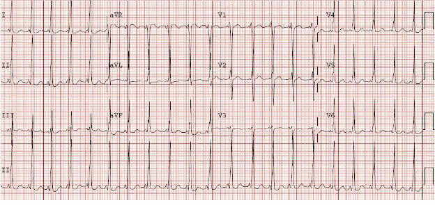
Figure 1. 12–lead electrocardiogram in sinus rhythm showing evidence for Wolff–Parkinson–White syndrome. The accessory pathway was likely in the right anterior, anterior-septal location.
-
1. Why esophageal and why not invasive electrophysiology study at this point?
Esophageal Study - The esophageal study showed a high-risk accessory pathway with an accessory pathway block cycle length of <200 msec and an accessory pathway effective refractory period of 400/240 msec. On isoproterenol, there was inducible regular wide complex tachycardia with a right bundle branch morphology to the QRS and a 1:1 V:A time on the esophageal electrodes. The tachycardia terminated with atrial pacing, suggesting orthodromic reciprocating tachycardia with aberrancy. There was no ectopic atrial tachycardia.
-
2. What are the options at this point?
Invasive Electrophysiology Study - The invasive electrophysiology study showed similar findings to the esophageal study.
Mapping and Cryoablation - Mapping was conducted in preexcited sinus rhythm. The three-dimensional (3D) ESI system (Endocardial Solutions, Inc., MN, United States) was utilized as well as fluoroscopic guidance. Mapping showed that the earliest activation was right anterior, just off the septum. The 4 mm tip small-curve cryoablation catheter was utilized. The catheter was placed at the site of the accessory pathway, and cryomapping energy to -40°C was applied. Within 13 sec of turning on energy, the ice ball formed at the tip of the catheter as evidenced by noise on the distal electrodes of the cryoablation catheter. Within seconds of ice ball formation, there was loss of accessory pathway conduction. The atrioventricular node conduction remained intact. Cryoablation was then applied at -70°C for a total of 4 min lesion. A freeze-thaw-freeze was conducted. The 4 mm tip cryoablation catheter was removed, and a 6 mm tip cryoablation catheter was advanced to the same location. An insurance lesion was placed at this same location with the larger tip catheter. Following these lesions, repeat atrial and ventricular extrastimulus testing showed no evidence for an accessory pathway and no further inducible tachyarrhythmias. The procedure was concluded. See Figures 2, 3, 4, and 5.
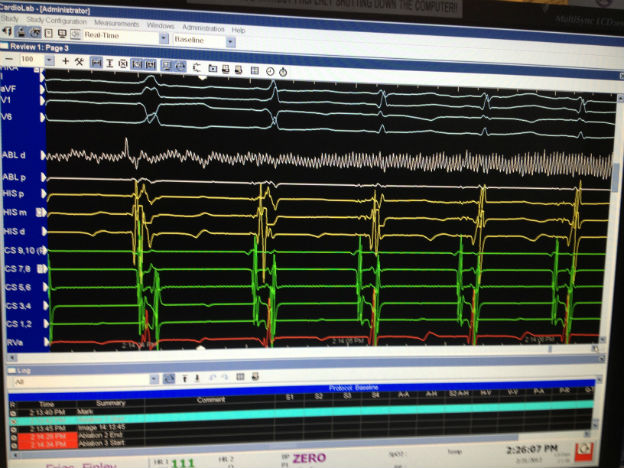
Figure 2. Intracardiac images of the site of successful cryoablation of the accessory pathway. The first beat in the screen was likely a premature ventricular beat. The second beat shows the surface and intracardiac signals for preexcitation. The third beats shows loss of preexcitation and normal atrioventricular nodal conduction. On the ablation catheter, one can see the noise and then the loss of signal as the ice ball is forming.
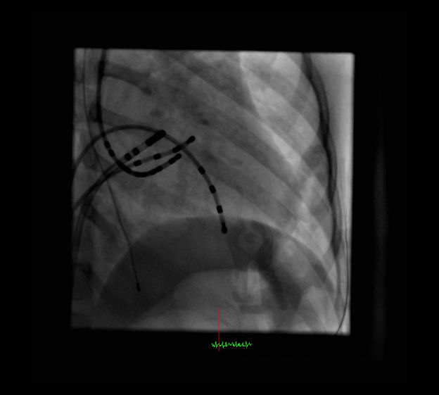
Figure 3. Fluoroscopic image in the right anterior oblique (RAO) 60° projection. This image shows the location of the ablation catheter at the site of a successful cryoablation lesion.
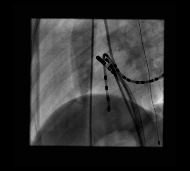
Figure 4. Fluoroscopic image in the left anterior oblique (LAO) 30° projections. These images show the location of the ablation catheter at the site of a successful cryoablation lesion.
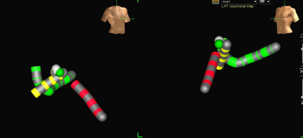
Figure 5. 3D ESI images of the site of successful cryoablation location. Catheters are as follows: ablation catheter (white with green tip), His bundle electrogram (yellow), right ventricular apex (red), and coronary sinus (green). The green ball is the site of successful cryoablation. The white balls are subsequent insurance lesions.
-
3. Why utilize the 4 mm tip cryoablation catheter?
-
4. Why go back with the 6 mm tip cryoablation catheter?
Correct Answer: It is the assessment and the experience of the operator that there is a relatively higher recurrence rate with the smaller tip catheter. Once there was successful cryoablation of the pathway with continued normal atrioventricular nodal conduction, it was felt that we could monitor atrioventricular nodal conduction safely while applying an insurance application with the larger tip catheter. Thus, the additional application was to decrease potential recurrence of the accessory pathway. See Figure 6.
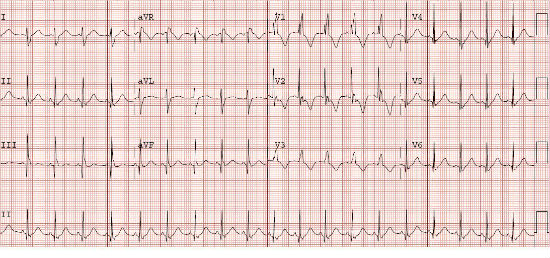
Figure 6. 12-lead surface electrocardiogram (ECG) the following day after cryoablation. This ECG shows normal sinus rhythm without preexcitation. There is right bundle branch block that occurred with catheter manipulation and had not yet resolved.